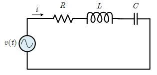
Resistor Impedance:
\( Z_R = R = \)?Ω
Inductor Impedance:
\( Z_L = jX_L = j2\pi fL = \)?Ω
Capacitor Impedance:
\( Z_C = -jX_C = \frac{-j}{2\pi fC} = \)?Ω
Total Impedance:
\( Z_T = Z_R+Z_L+Z_C = \)?Ω
Input Voltage:
\( V = \frac{V_m}{\sqrt{2}}\angle \theta_v = \)
?
V
\( V_{rms} = \|V\| = \frac{V_m}{\sqrt{2}} = \)
?
V
Resistor Voltage:
\( V_R = \frac{Z_R}{Z_T}V = \)
?
V
\( v_R(t) = \)
?
V
Inductor Voltage:
\( V_L = \frac{Z_L}{Z_T}V = \)
?
V
\( v_L(t) = \)
?
V
Capacitor Voltage:
\( V_C = \frac{Z_C}{Z_T}V = \)
?
V
\( v_C(t) = \)
?
V
Current:
\( I = \frac{V}{Z_T} = \)
?
A
\( I_{rms} = \|I\| = \)
?
A
\( i(t) = \)
?
A
Active Power:
\( P = V_{rms}I_{rms}cos(\theta_v-\theta_i) = \)?W